
Brake mechanism with a device for slowing down the vehicle
Brake mechanism with a device for slowing down the vehicle
Technical field
The braking mechanism with a vehicle deceleration device belongs to the production of vehicles and can be used in a mechanical braking system.
State of the art
For the first time, the brake system was used in horse-drawn vehicles, the wheel braking of which occurs through a hinge system. At the same time, a wooden block presses down on the wheel and slows it down.
https://ru.wikipedia.org/wiki/%D0%9C%D0%B5%D1%85%D0%B0%D0%BD%D0%B8%D1%87%0%B5%D1%81%D0%BA%D0%B8%D0%B9_%D1%82%D0%BE%D1%80%D0%BC%D0%BE%D0%B7
The brake mechanism has not undergone significant changes for five thousand years, which is why such harmful sliding friction has been preserved in it. Known multi-disc brake Ausco. The body of its brake mechanism consists of two parts, in the inner cavity of which there are 12 brake discs. The brake has a manual stroke control of the retaining disk (Brake systems of vehicles. L.V. Mashchenko, V.G. Rozanov. M.: Transport, 1972, p. 132-133.).
The closest analogue of the proposed brake is «Braking device of mechanical vehicles» — patent RU 2258162.
The disadvantage of the noted device is the complexity of the design — a large number of small parts, low reliability, less susceptibility to repair — if there are cracks on the friction materials, it comes to the need to change the disk. In addition, a large amount of product resulting from wear gets between the discs and reduces braking efficiency, and pad wear products pollute the environment.
The technical result of the proposed invention is to increase the reliability and durability of the brake, simplify the design. It is mainly aimed at preventing the release of harmful substances into the atmosphere/environment due to sliding friction. The device, due to its design, is more efficient not for instant / hard braking, but for delaying / stopping the stroke.
The technical result is achieved by the fact that the brake device for slowing down the vehicle, containing a brake disc fixed to the wheel axle, and on the support hub — a housing with transverse guides, with at least one slide installed in them and a braking element for interacting with the brake disc,
There are the following distinguishing features:
the braking element is made in the form of a rolling bearing enclosing the brake disk, and radially oriented elastic elements are fixed on the brake disk, the other ends of which adjoin the inner surface of the inner ring of said rolling bearing with a running clearance or clearance-free clearance.
The brake device for delaying the vehicle is represented by figures, which show:
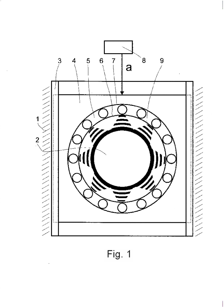
In FIG. 1 — general view of the device schematically, in the running state;
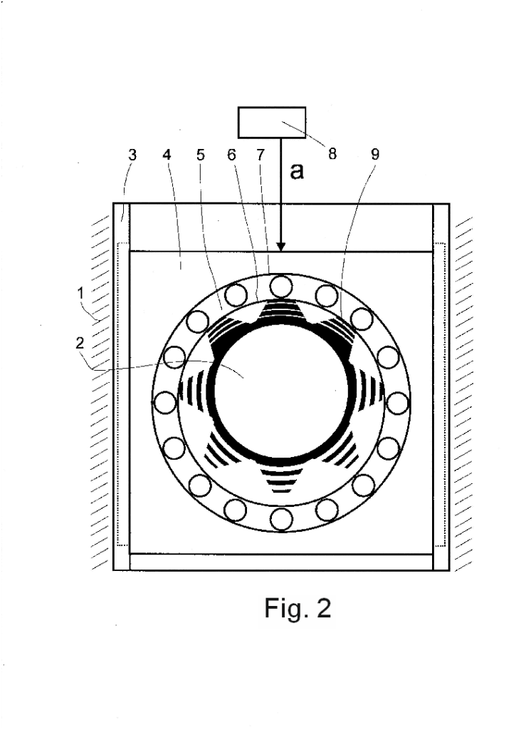
In FIG. 2 — general view of the device schematically, in the state of delay / braking of the course.
The braking device for slowing down the vehicle comprises a body 1 fixed on the wheel support hub, a disk 2 with the possibility of engagement engagement with an external object. Slider 4 with radial rolling bearing 5, with rings 6 and 7 is installed in the housing 1 in guides with the possibility of radial movement. Slider 4 is connected to the braking control body/means/drive 8. Between one of the rings (internal) 6 of bearing 5 and disk 2 installed radially oriented elastic elements 9, for example, springs. In this case, one ends of the elastic elements 9 are rigidly connected to the disk 2, and the other ends are in light contact, or better with a small gap (to eliminate unwanted friction during the course) adjacent to the inner surface of the inner ring 6 of the bearing 5.
The braking device works as follows. The rotation of the disk 2 together with the rotation of the wheel during the course of the vehicle. At the same time, during the course, the disc 2 and the bearing 5 are located concentrically and the process of rotation of the disc 2 occurs without slowing down and without braking. At this time, the inner ring 6 of the bearing 5, due to contact with the springs 9, will possibly be captured to rotate together with the disk 2 as a whole, or (if there is a radial clearance with the springs 9) will stand still — in both cases it does not cause resistance to running . To decelerate or brake with the help of the control drive 8, the slide 4 is moved in the direction «a» in the guides 3, respectively, and the bearing 5. Its inner ring 6 presses on the springs located in the sector on one side of the disk 2 and compresses them. In the sector on the other side of the disk 2, the springs 9 located at this moment are free from interaction, but at the same time, the movement, rotation of the disk 2 and the captured rotation of the inner ring 6 of the bearing 5 continues. Accordingly, the inner ring 6 of the bearing 5 continues to alternately (against rotation) compress the springs 9. In this case, the disc 2 is forced to overcome the large forces of the compressed springs 9. The more the mentioned bearing 5 moves in the radial direction, the more the springs 9 are compressed, the more is applied to rotating disk 2 the resistance force and slows down/stops the vehicle wheel associated with it.
As can be seen from the operation of the device, during deceleration and braking, pads sliding on the discs are not used. Unlike all previous braking devices, the proposed device does not use harmful sliding friction, it is replaced by rolling friction and compression of elastic elements, which determines a causal relationship between the distinctive features and the achieved result.
GreenBrake is mechanical braking device and at the same time works without brake pads, pneumatics, dry sliding friction and many other such parts.
Abstract
CLAIMS
A brake device relates to vehicle production and can be used in a mechanical brake system. The brake device is designed to prevent emission of harmful substances into the atmosphere/environment due to sliding friction. The brake device for slowing vehicle movement comprises a brake disk which is affixed to a wheel axle, and a housing with transverse guides which is affixed to a support hub, at least one slide and braking element being installed on the transverse guides so as to interact with the brake disk. The braking element is designed as a roller bearing enclosing the brake disk, with radially oriented resilient elements affixed to the brake disk, the other ends of the elastic elements adjoining an inner surface of an inner ring of the aforementioned roller bearing with a running clearance or without a clearance.
A braking device for slowing vehicle movement, comprising a brake disc affixed to the wheel axle, and a housing with transverse guides affixed to a support hub, at least one slide installed in a support hub with a braking element for interacting with the brake disc, wherein the braking element is designed as a roller bearing enclosing the brake disk, and on the brake disk radially oriented springy elements are affixed, the other ends of which with a running clearance or without a clearance adjoin the inner surface of the inner ring of the said roller bearing.
Technical field
Brake mechanism with a device for slowing down the vehicle
Technical field
The braking mechanism with a vehicle deceleration device belongs to the production of vehicles and can be used in a mechanical braking system.
State of the art
For the first time, the brake system was used in horse-drawn vehicles, the wheel braking of which occurs through a hinge system. At the same time, a wooden block presses down on the wheel and slows it down.
https://ru.wikipedia.org/wiki/%D0%9C%D0%B5%D1%85%D0%B0%D0%BD%D0%B8%D1%87%0%B5%D1%81%D0%BA%D0%B8%D0%B9_%D1%82%D0%BE%D1%80%D0%BC%D0%BE%D0%B7
The brake mechanism has not undergone significant changes for five thousand years, which is why such harmful sliding friction has been preserved in it. Known multi-disc brake Ausco. The body of its brake mechanism consists of two parts, in the inner cavity of which there are 12 brake discs. The brake has a manual stroke control of the retaining disk (Brake systems of vehicles. L.V. Mashchenko, V.G. Rozanov. M.: Transport, 1972, p. 132-133.).
The closest analogue of the proposed brake is «Braking device of mechanical vehicles» — patent RU 2258162.
The disadvantage of the noted device is the complexity of the design — a large number of small parts, low reliability, less susceptibility to repair — if there are cracks on the friction materials, it comes to the need to change the disk. In addition, a large amount of product resulting from wear gets between the discs and reduces braking efficiency, and pad wear products pollute the environment.
The technical result of the proposed invention is to increase the reliability and durability of the brake, simplify the design. It is mainly aimed at preventing the release of harmful substances into the atmosphere/environment due to sliding friction. The device, due to its design, is more efficient not for instant / hard braking, but for delaying / stopping the stroke.
The technical result is achieved by the fact that the brake device for slowing down the vehicle, containing a brake disc fixed to the wheel axle, and on the support hub — a housing with transverse guides, with at least one slide installed in them and a braking element for interacting with the brake disc,
There are the following distinguishing features:
the braking element is made in the form of a rolling bearing enclosing the brake disk, and radially oriented elastic elements are fixed on the brake disk, the other ends of which adjoin the inner surface of the inner ring of said rolling bearing with a running clearance or clearance-free clearance.
The brake device for delaying the vehicle is represented by figures, which show:
In FIG. 1 — general view of the device schematically, in the running state;
In FIG. 2 — general view of the device schematically, in the state of delay / braking of the course.
The braking device for slowing down the vehicle comprises a body 1 fixed on the wheel support hub, a disk 2 with the possibility of engagement engagement with an external object. Slider 4 with radial rolling bearing 5, with rings 6 and 7 is installed in the housing 1 in guides with the possibility of radial movement. Slider 4 is connected to the braking control body/means/drive 8. Between one of the rings (internal) 6 of bearing 5 and disk 2 installed radially oriented elastic elements 9, for example, springs. In this case, one ends of the elastic elements 9 are rigidly connected to the disk 2, and the other ends are in light contact, or better with a small gap (to eliminate unwanted friction during the course) adjacent to the inner surface of the inner ring 6 of the bearing 5.
The braking device works as follows. The rotation of the disk 2 together with the rotation of the wheel during the course of the vehicle. At the same time, during the course, the disc 2 and the bearing 5 are located concentrically and the process of rotation of the disc 2 occurs without slowing down and without braking. At this time, the inner ring 6 of the bearing 5, due to contact with the springs 9, will possibly be captured to rotate together with the disk 2 as a whole, or (if there is a radial clearance with the springs 9) will stand still — in both cases it does not cause resistance to running . To decelerate or brake with the help of the control drive 8, the slide 4 is moved in the direction «a» in the guides 3, respectively, and the bearing 5. Its inner ring 6 presses on the springs located in the sector on one side of the disk 2 and compresses them. In the sector on the other side of the disk 2, the springs 9 located at this moment are free from interaction, but at the same time, the movement, rotation of the disk 2 and the captured rotation of the inner ring 6 of the bearing 5 continues. Accordingly, the inner ring 6 of the bearing 5 continues to alternately (against rotation) compress the springs 9. In this case, the disc 2 is forced to overcome the large forces of the compressed springs 9. The more the mentioned bearing 5 moves in the radial direction, the more the springs 9 are compressed, the more is applied to rotating disk 2 the resistance force and slows down/stops the vehicle wheel associated with it.
As can be seen from the operation of the device, during deceleration and braking, pads sliding on the discs are not used. Unlike all previous braking devices, the proposed device does not use harmful sliding friction, it is replaced by rolling friction and compression of elastic elements, which determines a causal relationship between the distinctive features and the achieved result.
Abstract
CLAIMS
A brake device relates to vehicle production and can be used in a mechanical brake system. The brake device is designed to prevent emission of harmful substances into the atmosphere/environment due to sliding friction. The brake device for slowing vehicle movement comprises a brake disk which is affixed to a wheel axle, and a housing with transverse guides which is affixed to a support hub, at least one slide and braking element being installed on the transverse guides so as to interact with the brake disk. The braking element is designed as a roller bearing enclosing the brake disk, with radially oriented resilient elements affixed to the brake disk, the other ends of the elastic elements adjoining an inner surface of an inner ring of the aforementioned roller bearing with a running clearance or without a clearance.
A braking device for slowing vehicle movement, comprising a brake disc affixed to the wheel axle, and a housing with transverse guides affixed to a support hub, at least one slide installed in a support hub with a braking element for interacting with the brake disc, wherein the braking element is designed as a roller bearing enclosing the brake disk, and on the brake disk radially oriented springy elements are affixed, the other ends of which with a running clearance or without a clearance adjoin the inner surface of the inner ring of the said roller bearing.

A 24830 Bremseinrichtung zur Verzögerung des Ganges eines Fahrzeugs
Die Erfindung betrifft eine Bremseinrichtung zur Verzögerung des Ganges eines Fahrzeugs und kann bei der Herstellung von Fahrzeugen im mechanischen Bremssystem verwendet werden.
Zum ersten Mal wurde ein Bremssystem im bespannten Verkehr verwendet, dessen Räderbremsung durch ein Scharniersystem erfolgte. Dabei drückt der Holzklotz an das Rad und bremst es.
Im Lauf von fünf Jahrhunderten hat das Bremssystem keine bedeutsamen Veränderungen erfahren, so dass in ihm die so schädliche Reibung des trockenen Gleitens erhalten geblieben ist.
Von Ausco ist eine Lamellenbremse bekannt. Der Körper ihres Bremssystems besteht aus zwei Teilen, in deren innerem Raum 12 Bremsdeckplatten/Scheiben angeordnet sind. Die Bremse hat einen Handversteller für die Gangverzögerung der Bremsdeckplatten/Scheiben (Bremssysteme für Fahrzeuge. L.W. Maschtschenko, W.G. Rosanov, M.:Transport, 1972, S.132-133).
Nähere Analoge zur angebotenen Bremse sind im Patent RU 258162 „Bremseinrichtung der mechanischen Fahrzeuge“ genannt.
Als Nachteil der genannten Einrichtung gilt die Komplexität der Konstruktion: große Menge von kleinen Details, niedrige Betriebszuverlässigkeit, Anfälligkeit zur Renovierung. Durch Einrisse auf den Reibstoffen entsteht die Notwendigkeit des Ersetzens der Bremsdeckplatte. Die große Menge von Verschleißprodukten zwischen den Bremsdeckplatten/Scheiben verringert die Bremseffizienz und belastet außerdem die Umwelt.
Aufgabe der vorliegenden Erfindung ist es, die Betriebszuverlässigkeit und die Nutzungsdauer der Bremsung zu steigern und die Konstruktion zu vereinfachen.
Es ist hauptsächlich auf ein Verhindern des Auswurfs von Schadstoffen durch die Reibung des Gleitens in die Umwelt gerichtet. Die Einrichtung nach ihrer konstruktiven Ausführung ist mit großer Effizienz nicht für momentale/robuste Bremsung, sondern zur Verzögerung/zum Anhalten des Ganges anwendbar.
Das technische Ergebnis wird dadurch erreicht, dass die Bremseinrichtung zur Verzögerung des Ganges des Fahrzeugs, enthalten auf dem Radachse befestigte Bremsendeckplatte/Scheibe und auf der Stütz von Bremstrommelnabe – Körper mit queren Führungsbahnen, mit mindestens einem darin eingebauten Schieber und Bremselement zur Koppelung mit der Bremsendeckplatte/Scheibe,
weisen folgene Merkmale nach:
Bremselement ist als Wälzlager Bremsendeckplatte/Scheibe umfassend ausgeführt und auf der Bremsendeckplatte/Scheibe radial orientierte biegsame Elemente befestigt, andere Enden deren mit Gangsspalte oder sich ohne Spalt an innere Fläche des inneren Ringes des genannten Wälzlager anlehnen.
Ein Ausführungsbeispiel der Erfindung wird anhand der Zeichnungen näher erläutert. Es zeigen:
Fig. 1 eine schematische Übersicht der Einrichtung im Gangstand und
Fig. 2 eine schematische Übersicht der Einrichtung im Stand der Verzögerung/Bremsung des Ganges.
Die Bremseinrichtung zur Verzögerung des Ganges eines Fahrzeugs enthält einen Körper 1, befestigt auf der Stütznabe des Rades und eine Bremsdeckplatte/Scheibe 2 mit der Möglichkeit einer Eingreifkoppelung mit dem Außenobjekt. Im Körper 1 in den Führungsbahnen mit der Möglichkeit der radialen Verstellung ist ein Schieber 4 mit radialem Wälzlager 5 und mit Ringen 6 und 7 angeordnet. Der Schieber 4 ist mit dem Organ/Mittel/Antrieb der Bremssteuerung 8 verbunden. Zwischen einem von Ringen (dem innerem) 6 vom Lager 5 und der Bremsdeckplatte/Scheibe sind radial orientierte biegsame Elemente 9, z. B. Federn angeordnet. Dabei ist eine der Endseiten der biegsamen Elemente 9 mit der Bremsdeckplatte/Scheibe verbunden, und die anderen Endseiten befinden sich in leichtem Kontakt bzw. mit kleinem Abstand (für die Ausschließung der unzulässiger Reibung beim Gang) und sich an innere Fläche des inneren Ringes 6 des Lagers 5 anlehnen.
Die Bremseinrichtung funktioniert folgenderweise:
Drehung der Bremsdeckplatte/Scheibe 2 zusammen mit der Drehung des Rades beim Gang des Fahrzeuges. Dabei sind die Bremsdeckplatte/Scheibe 2 und das Lager 5 konzentrisch angeordnet, und der Drehungsvorgang der Bremsdeckplatte/Scheibe 2 wird ohne Verzögerung und Bremsung durchgeführt. In diesem Moment kann der innere Ring 6 des Lagers 5 wegen des Anliegens mit den Federn 9 angefasst und zusammen mit der Bremsdeckplatte/Scheibe 2 gedreht werden, wie eine Ganze oder (wenn mit den Federn 9 gibt es einen Abstand) wird an der Stelle bleiben. In beiden Fällen wird kein Widerstand zum Gang verursacht werden. Für die Gangverzögerung oder Bremsung mittels Steuerungsmittelantrieb 8 führt man eine Verschiebung in Richtung „a“ von Schieber 4 in den Führungsbahnen 3, entsprechend auch des Lagers 5 durch. Sein innerer Ring 6 drückt auf im Sektor auf einer Seite angeordnete Feder der Bremsdeckplatte/Scheibe 2 und spannt sie beide. Im Sektor der anderen Seite der Bremsdeckplatte/Scheibe 2 sind die angeordneten Federn 9 in diesem Moment vom Zusammenwirken frei, aber gleichzeitig werden sich der Gang, die Drehung der Bremsdeckplatte/Scheibe 2 und die angefasste Drehung des inneren Ringes 6 des Lagers 5 fortsetzen. Entsprechend wird der innere Ring 6 des Lagers 5 nacheinander (in Gegenrichtung der Drehung) die Federn 9 spannen. Dabei ist die Bremsdeckplatte/Scheibe 2 gezwungen, die große Kraft der gespannten Federn 9 zu überwinden. Je mehr das genannte Lager 5 in die radiale Richtung geschoben wird, desto mehr werden die Federn 9 gespannt und wird sich mehr Kraft an die drehende Bremsdeckplatte/Scheibe 2 anlehnen und das mit ihnen verbundene Rad vom Fahrzeug verzögern/anhalten.
Wie aus dem Arbeitsvorgang der Einrichtung zu sehen ist, werden im Lauf der Verzögerung und Bremsung die auf den Bremsdeckplatten/Scheiben gleitenden Klötze nicht benutzt. Im Vergleich zu allen vorherigen Bremseinrichtungen wird in der angebotenen Einrichtung die schädliche Reibung des trockenen Gleitens nicht verwendet. Sie ist durch Rollwiderstand/Rollreibung und Spannung der biegsamen Elemente ersetzt, was einen Ursache-Wirkungs-Zusammenhang zwischen den kennzeichnenden Merkmalen und dem erreichten Ergebnis verursacht.
P a t e n t a n s p r u c h
Bremseinrichtung zur Verzögerung des Ganges eines Fahrzeugs, die auf der Radachse eine befestigte Bremsdeckplatte und auf der Stütznabe Körper mit Führungsbahnen mit in ihnen angeordneten mindestens einem Schieber und einem bremselement für das zusammenwirken mit der bremsdeckplatte enthält, dadurch gekennzeichnet, dass das bremselement als wälzlager ausgeführt ist, das die Bremsdeckplatte umfasst und dass auf der bremsdeckplatte radial orientierte biegsame elemente befestigt sind, an andere enden deren mit gangsspalte oder sich ohne spalt an innere Fläche des inneren Ringes des genannten Wälzlager anlehnen.
Die Bremseinrichtung gehört zur Fahrzeugherstellung und kann bei mechanischen Bremssystemen verwendet werden. Sie ist auf das Verhindern von Auswurf von Schadstoffen auf Grund der Reibung des Gleitens in die Umwelt gerichtet.
Die Bremseinrichtung zur Verzögerung des Ganges eines Fahrzeugs enthält eine auf der Radachse befestigte Bremsdeckplatte und auf der Stütznabe Körper mit Führungsbahnen mit in ihnen angeordneten mindestens einem Schieber und Bremselementen für das Zusammenwirken mit der Bremsdeckplatte. Das Bremselement ist als Wälzlager ausgeführt, das die Bremsdeckplatte umfasst. Auf der Bremsdeckplatte sind radial orientierte biegsame Elemente befestigt, an deren Enden mit Gangspalte oder ohne Spalt an innere Fläche des inneren Ringes des genannten Wälzlager anlehnen.
Report
The braking device belongs to the production of vehicles and can be used in a mechanical braking system. It is aimed at eliminating the release of harmful substances into the atmosphere/environment due to sliding friction.
The braking device for slowing down the vehicle contains a brake disc fixed to the wheel axle, and on the support hub there is a housing with transverse guides, with at least one slide installed in them and a braking element for interaction with the brake disc. The braking element is made in the form of a rolling bearing covering the brake disc, and radially oriented elastic elements are fixed on the brake disc, the other ends of which are adjacent to the inner surface of the inner ring of the said rolling bearing with a running gap or without a gap.


